

In the last few installments, we looked at using the Tang Nano 20K with both the GOWIN tools and some open-source tools. The open-source tools certainly had the advantage of letting you simulate and debug your design before sending it to the actual chip. However, as we’ll see, the GOWIN tools include a very easy-to-use, capable logic analyzer.
Setup
First, you’ll need a GAO config file. When you create one in the editor, you are given a number of complex options. With an active GAO file, the tool builds a logic analyzer into your design, and the file sets the trigger conditions.
Here’s a tip. You can only have one active GAO file. Sometimes you don’t want the logic analyzer. Other times you might want an alternate configuration. If you right-click almost any file in the IDE’s Design tab, you’ll see you can disable it. That gives it a big red X and excludes it from future builds. Well, at least until you enable it again. This lets you pick between multiple GAO files, or even multiple Verilog files, for a particular build (e.g., one for tests and another for production).
If you create a GAO file from scratch, it will ask you if you want “Lite Mode.” As far as I can tell, you will never want this mode. Always use Standard Mode. In addition, you nearly always want RTL mode, which shows you (mostly) the symbols you’ve defined and not the ones added during processing.
You can find the entire manual online, of course. However, the video below and the rest of the post will get you started quickly.
GAO Basics
To set up probing, we need to understand the design, so the rest of this post covers the Verilog we’ll use to test the logic analyzer feature, and you’ll see how the analyzer works in a video. Here are a few sneak peeks at what the analyzer output we’ll see at the end looks like:
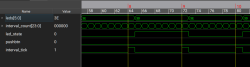
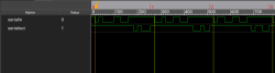
The left-hand image shows the pulse that flips the LEDs, which is tricky because the sampling clock is 27 MHz. The right-hand side shows serial data and uses a slower clock specifically used for debugging.
Inside the Verilog
Verilog can be dangerous. If you already know how to program, Verilog looks just enough like a programming language to encourage you to think about it the wrong way. You can’t think of Verilog as code. It describes how you want hardware to behave. A key part of that is clocks.
Most practical digital systems have some kind of clock that makes things work. Very simple things like our last example might not need them, but practical systems almost always do. In theory, you can make asynchronous logic, but it is very difficult. Synchronous logic — those with a clock controlling things — is vastly more common.
Why Clocks?
We think of signals as changing instantly, but they don’t. They change at slightly different times for many reasons: wire length, capacitance, differences in device construction, temperature, and probably many other things. So let’s think of an exaggerated example. Suppose you have a super safe car. If it detects the motor is running and the door is open, it kills the engine. That’s an AND gate, and for the purposes of exaggeration, suppose the signals from the door and the engine that feed the AND gate take a random amount of time between 100 and 900 milliseconds to get to the AND gate.
Normally, it wouldn’t matter much. You close the door, check your mirror, turn on your playlist, and you start the car. But suppose you were in a panic. You jump in the car and immediately try to start it. The engine start signal could get there before the signal that the door is open turns off. Suddenly, your engine cuts off right after you start it. Not cool.
This is a bit made up, but the problem is real. Suppose you want to add two numbers. One number changes from 11 to 22 while the other changes from 5 to 10. You want 16 and 32 as results. But instead you get 16, 27, and then 32. Or maybe 16, 21, and then 32. Still not cool.
So clocks basically let you give everything enough time to settle down and then figure out the output. Those outputs will stay stable until the next clock. That’s grossly oversimplified, but we’ll talk more about it later. Each thing in your design takes some time, and the longest time, in general, will dictate your maximum clock rate. So if one part of your design takes a microsecond to reliably change, your frequency will have to have a longer period than that.
Check out the example file. This is regular Verilog, although SystemVerilog (.sv files) has some advantages that you can utilize that I’ll point out. The example we’ve been using is a very simple design that just drives some LEDs on the 20K board. The input clock will be 27 MHz, so to make the LEDs blink, we will need to count many clock cycles and only change the LEDs sometimes.
In addition, it is going to use IP — predefined blocks — to build a UART. The function is simple and contrived. By default, entering a character through the UART will echo it. However, if you push the user button on the board, it will switch the board to a mode where it adds one to the character before resending it. If you push the button again, the output will be a straight echo. When you push the button in either case, the device will send an asterisk.
From the Top
At the top of the file you’ll see this line:
default nettype none
This is a good idea because without it, Verilog will happily create new nets from typos. For example:
countt=count+1;
Now count doesn’t change, but a new wire, countt is set and never used. The only problem is that some of the GOWIN IP expects the default nettype to be wire so at the end of your files, you need to put it back:
default nettype wire
Another quirk is that while some tools will realize that if you specify an input or an output, it should infer that you mean a wire unless you say otherwise. The GOWIN tools will refuse to do this if you set the default type to none.
Modular
The next part is the led module. This is a reusable piece, in theory. However, it is also our top block. The #() syntax allows me to set some parameters you can change when you create one of these modules, as well as the defaults. For example, in the previous testbench I wrote:
led #(.CLOCK_FREQUENCY(10, .INTERVAL_MS(1000)) uut(.reset(reset), .Clock(clk)...
This sets a slow clock and interval for simulation purposes instead of using the defaults. Not all modules have parameters. After that, though, there is what looks like an argument list of inputs and outputs. These are the ports you can use if this isn’t your top module, but since this one is the top module, we’ll need constraints to assign them to particular pins on the FPGA.
The localparam statements are like #defines in C, and we use them to set the required counter and figure out the number of bits we need for the counter ($clog2 gives us the base 2 logarithm at compile time).
Most of the time we deal with wires. Something has to drive them. They are perfect for connecting to things. But then there are also regs. You might think these are flip-flops, but that’s not exactly true. They are just Verilog variables, if you will.
It is easy to think of wires and regs as being 1 or 0, but it turns out Verilog also supports values like X (unknown) and Z (sort of like open collector). In fact, SystemVerilog allows you to write logic instead of wire or reg, something we’ll talk about soon. However, there is so much “plain” Verilog out there that it is important to understand it even if you plan to use the more modern SystemVerilog in your own work.
Look at this line:
reg [COUNT_BITS-1:0] interval_count;
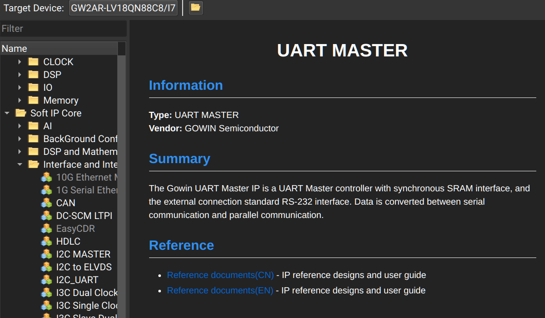
The IP Generator has plenty of choices and links to documentation.
This tells us that we have a reg named interval_count. It has bits that range from bit 0 (least significant) to COUNT_BITS-1. Note that you can reverse those if it makes sense for your design. Or start at bit 1, for example. This is not an array, although Verilog does support arrays. This is a multi-bit variable. If you don’t specify the bits (like the interval_tick definition that appears next) then the variable is a single bit.
The next bit of code defines reg and wire variables that will connect to the UART. For now, we aren’t building our own UART. We’re using the IP provided by GOWIN. One problem with this is that it is really made to connect to a microprocessor, so we are going to cheat a little to make it simple to use. You can insert IP into a project from the Tools menu under IP Core Generator.
The final setup section handles the pushbutton input and LED state. The pushbuttons are not synchronized to the clock and this can lead to a major problem. Plus, mechanical switches can bounce — that is, they don’t go off then on. They go off, on, off, on, off, on, off, and then — after a few milliseconds — they settle in the on state. There is a debounce module included to help with these problems. For now, we’ll just use it like we’ll use the UART, even though this module is in debounce.v.
Instantiation
Here’s how we create a debounce module. You could, in theory, create as many as you like:
debounce #(
.CLOCK_FREQUENCY (CLOCK_FREQUENCY),
.DEBOUNCE_MS (10)
) button_filter (
.Clock (Clock),
.reset (reset),
.noisy_button (pushbtn),
.clean_button (button)
);
The name of the instance is button_filter, and we’ve set parameters to tell it our clock frequency and the debounce time, which is 10 milliseconds. The connectors are the clock and reset lines, along with the button input and a clean version of the button as an output.
Assignment: UART
There are a few lines that start with assign. These are Verilog’s soldering irons. You can connect a wire output to some variable or expression, and then that is what that wire will be. We’ve seen that in the earlier LED-only demos.
Then there is a much more complex instantiation of the UART. Although it has more ins and outs, it is basically the same as connecting the debounce module. Note that in some cases I just force fixed data to a pin (e.g., 3’b001, which is a three-bit binary constant, or 8’hff, which is an 8-bit FF hex. Some connections are wires or regs. Some are expressions like ~reset (the inverse of reset).
The upshot is simple. When uart_rx_ready_n goes low, you can read a character from uart_rx_data. The transmit has a similar setup.
The Flop
The rest of the file has three always expressions. There are two things you can do with always (in fact, SystemVerilog separates these out as we will see in the future). For now, we will focus on how to write clocked flip flops using always @.
The simplest one is the last one that toggles the LED state:
always @(posedge Clock) begin
if (reset)
led_state <= 1'b0;
else if (interval_tick)
led_state <= ~led_state;
end
This will create a flip-flop that triggers on the positive edge of Clock. If the reset line is high, the flip-flop will set led_state to 0. Otherwise, it will set the led state to the inverse of whatever it was before.
There are a few things to note here. First, led_state can’t be set anywhere else but inside this always block. The other problem is a bit trickier. Note that the assignments use <= and not =. You could write = but that leads to a problem. Imagine this code inside an always block:
qout=3'b000;
if (b) quot=~quot;
Verilog would interpret this to mean that quot should be set to 0 before the next line. Remember, though, that Verilog at “run time” doesn’t step through code line-by-line. So it would infer a latch to hold this value and feed it to the logic that handles the second line.
Not only is this not what you want, but it generates strange things on the device that will not operate efficiently. Instead, you want to use the <= assignment. In essence, every value of quot read in the always block will be whatever quot was at the clock edge. Then, at the end of the block, the last <= assignment “wins.”
This is probably what you really meant anyway and avoids creating strange latches that will, at best, slow down your design. In practice, you can think of it as the flip-flops will capture inputs on the clock edge, then produce outputs that will be ready (at least) by the next clock edge.
Metastability
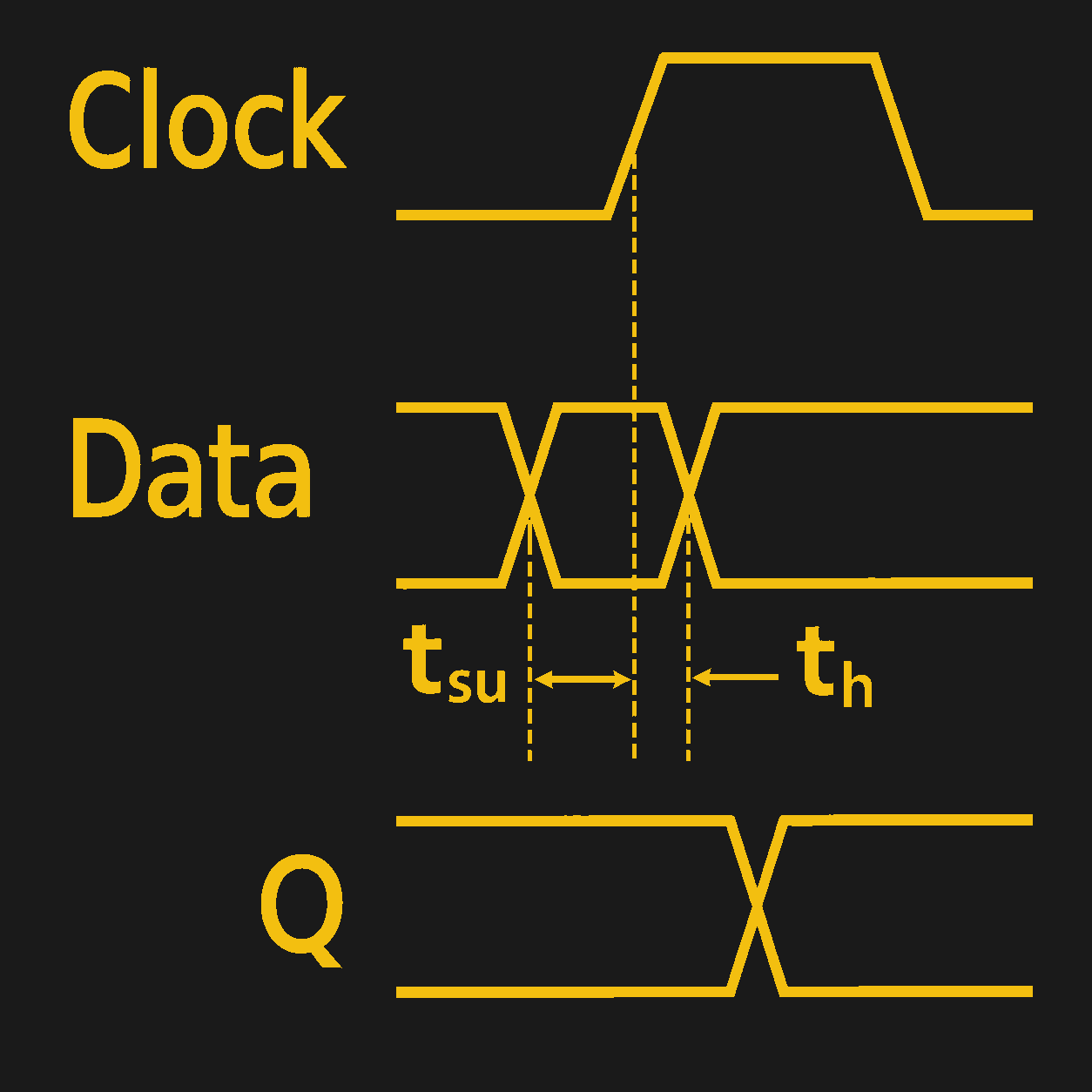
Data must be stable for the setup time through the hold time.
I mentioned the debounce module did two things: debounces the mechanical switch and synchronizes with the clock. The problem is that we imagine flip-flops to be perfect but, of course, they are not. Any practical flip-flop has a setup time and a hold time. Imagine a very bad flip-flop that had a setup time of 100 milliseconds and a hold time of 50 milliseconds. That would mean that an input has to be stable for at least 100 milliseconds before the clock trigger and can’t change until 50 milliseconds after the trigger.
This is one thing that affects your maximum clock speed. Logic has to have time to stabilize before the clock triggers. But if something is coming from another clock or, worse still, asynchronously, then you run a risk. If the flip-flop’s requirements are not met, it can go metastable, where it could be in an indeterminate state or even oscillate wildly.
The most common way to combat this is to delay the signal with a few flip-flops. The idea is that even if one flip-flop goes metastable, it won’t go all through the system. Just something to be aware of if you deal with something asynchronous or try to connect flip-flops using one clock to those using a different clock.
If a Picture’s Worth…
Now that we know what’s going on in the Verilog, we’re ready to set up the logic analyzer. You can find out how that works in the video below. You can also grab the files on GitHub.
Be sure to drop by the Discord. If you need a refresher on digital logic, there are always the FPGA Bootcamps.