
Last Friday we looked at Wild Planet’s Spy Video TRAKR programmable RC vehicle mostly from an end user perspective.*Much of our weekend was spent dismantling and photographing the device’s internal works, and poring over code and documentation, in order to better gauge the TRAKR’s true hackability.*Our prior review included some erroneous speculation…we can clarify a number of details now, and forge ahead with entirely*new erroneous speculation!
Our plan with this teardown is to*establish more concrete details of what’s hackable inside the device, what’s not, and*to help nail down some of the unstated hardware specifications.
We incorrectly reported that no programming documentation or compiler is yet available. Turns out all this information was simply tucked away in a help section of the TRAKR web site, not on the “App BUILDR” page where we expected it. Derp! These resources are still in a rough state,*yet proved to be a far more valuable source of information than the physical teardown.*C code and PDFs aren’t very photogenic though, so we’ve got plenty of circuit board pr0n to start with!
Inside the Remote
There’s not as much to see or do inside the TRAKR remote, so we’ll power through that first.

The concealed rear USB port was mentioned last time, which we’ve been informed is to allow for field-upgradeable firmware.*If you don’t mind being tethered to one spot, we discovered the remote can also be powered from a USB hub, or even from the TRAKR’s own USB host port.
In another nod to tinkerer-friendly design, both the remote and the TRAKR are held together with identical Phillips screws throughout, recessed but not hidden under stickers or rubber pads.

The LCD screen is one typically seen in cell phones, 15-bit color at 160×120 pixels.

The “Bot Switch PCB” has just some switches and passive components. SW1 and SW4 have dedicated purposes (home menu and power), but the functions of the others are defined by individual apps. If you’re looking for GPIO lines to hack in the remote, this might be your best bet.

The underside of the main remote PCB has some exposed pads, but there are no through-hole solder points. The pad labeled “V0_TVOUT” caught our attention, thinking it might provide a composite video signal, but this turned out not to be the case, or at least it’s not enabled in the present firmware. J9 looks like a JTAG header.

A few more test points tucked beneath the LCD.

2 megabyte SDRAM and 1 megabyte SPI flash in the remote.

We were really hoping that the joysticks might be analog internally, but no such luck…they’re simple forward/reverse switches. Even if replaced with potentiometers, without access to the firmware source there’s no way of communicating this information to the TRAKR.

The remote and TRAKR have outwardly-identical radio transceivers. They’re rather well-sealed and we’ve not dismantled them further yet, but recall hearing they’re based on a Nordic 2.4 GHz part.*Wild Planet claims that with a forthcoming firmware change, they’ll be WiFi-capable. We remain hopeful but skeptical — it seems far more likely that the remote’s rear USB port will come into play, or in the interim perhaps one of the SparkFun Nordic options will prove a viable choice for PC control.
Inside the TRAKR

Removing the screws is straightforward, but fully removing the lid from the TRAKR requires several cables be detached first — and they’ve all been glued in place for reliability. We just cut through the glue with an X-acto knife and pried a bit, but maybe it can be more delicately dissolved or melted.

The right side of the main board (turned sideways here) focuses on connectivity and the CPU. The ribbon cable at left leads to the camera. The pair of two-pin headers lead to the microphone and front accessory bump switch. The purpose of the unpopulated SW1 isn’t known — it might be that early designs featured an additional rear or top switch, now vestigial. The larger headers lead to the radio module and the trim pots and recessed reset/debug switches on the bot’s undercarriage.
No need to get through that epoxy blob. Digging through configuration files for the compiler, the chip appears to be a Nuvoton W55VA91, featuring an ARM926EJ core running at 192 MHz, and hardware-assisted JPEG codec.

The middle section of the board is what TRAKR-hackers will become most acquainted with. JACK3, the vertical row of pads in the center, contains 8 digital GPIO lines and one analog input, with 0.1″ pin spacing. JACK4 looks like a JTAG port, with 2mm pin spacing. Below that is the connector for the USB host port, and the second (unpopulated) port at the right can be used as a 5V source. It’s a real shame that power and ground were overlooked on JACK3 despite its proximity to those traces. With the addition of power traces and a row header soldered in place, this would have made a nice standardized riser for small add-ons, much like the ecosystem of Arduino “shields” that has taken off.

Left side of the board is devoted mainly to power and motor control. The red/black wires at left lead to the battery compartment. Connector above that is for the speaker. The two 3-pin connectors at the bottom lead to the left and right motors, with the H-bridge driver circuit above that.
By the way — if you dismantle your TRAKR, when it comes time to put it back together, there are four screw holes that aren’t actually used despite their labeling on the silkscreen layer. You can see three of these in the photo above, and the fourth in a prior photo near the camera connector.*Forcing screws in could damage one of the motor cables underneath!

Little to see on the underside. Another inactive V0_TVOUT pad taunts us! This side is dominated mostly by the SD card socket, and…

…ample 8 megabyte SDRAM, 2 megabyte flash. Together with the SD slot, USB and ARM9 CPU, we’re*anticipating ucLinux and DOOM to be ported in 3…2…1…

The USB host port is on a small daughter board, and each of the motors has some local driver circuitry as well.

Each motor is driven through a reduction gearbox. They operate quietly with only a slight amount of slop. As with the radio, we’ve not further dismantled these yet.

Though not powered, the front wheels aren’t as boring as we first thought. This rack and spring mechanism keeps a constant tension on the rubber tread belts, allowing them to flex and maintain traction as the TRAKR drives over various terrain.

The partly-disassembled camera pivot mechanism. Two small rubber pads provide just enough friction to hold the camera in its set position, yet still allow it to pivot easily. If attempting to add servo control to the camera, removing those pads will likely help.
The camera is connected to the main PCB with a 24-conductor flex cable, 0.5mm pitch and about 6 inches long. Mounting the camera in a higher position might best be done by replacing the entire cable with a longer one,*but we’ve yet to locate a*suitable match from a source such as DigiKey.

Extracting the camera PCB from its housing, we were greeted with a low-hanging hack opportunity: the board was designed to accommodate multiple LEDs, but in practice shipped with just one large one in place. Boosting the light output should be a very simple matter of adding the missing resistors and LEDs, though you’ll need to drill holes through the case or run wires to mount the LEDs externally.
We’re not 100% certain of the camera sensor yet. From PR materials at Maker Faire, we know it’s from OmniVision, but don’t know the exact model. Based on size and specifications, the OV7670 looks like a possibility, in which case it should be capable of full VGA resolution, not just the QVGA output we’ve seen.

The “accessory port” is just a passive attachment point to clip things on; it resembles a headphone jack, but isn’t. There is a pushbutton switch behind it, maybe an interactive cat-poking stick is planned.

The artist’s signature.
Reassembly was straightforward. Cable connectors are keyed for orientation, and for those that aren’t a unique size, the correct positions can be inferred from cable length. And there was no mysterious “extra screw” at the end — everything went together easily and worked on the first try.
Passengers
Some readers have asked about mounting external microcontrollers or other devices to the rear transport deck. Adding*a microcontroller isn’t an entirely ridiculous prospect — even though the TRAKR’s CPU has far more “oomph,” it remains to be seen if the GPIO lines are suited to tasks such as accurate*PWM for servo control. Delegating such tasks may prove helpful, or even necessary.*The usable area of the transport deck is a bit over five inches wide and three inches deep,*and a couple of rubber bands or some foam tape will hold most boards securely. With the deck removed, the recessed notch above the battery bay is such a perfect size for certain things, it’s almost uncanny. Did [Dave] plan this?

Arduino, natch. Small devices like this can be powered from the TRAKR’s USB host port, but without an FTDI driver on the host side this connection can’t be used for serial communication.
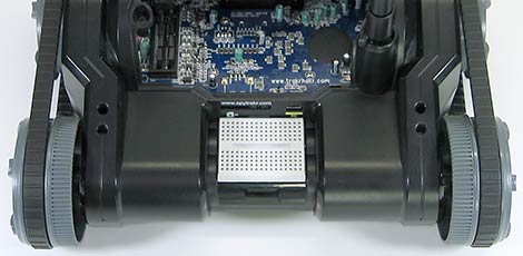
Half-size and quarter-size breadboards fit exceedingly well, almost snapping into place. But anything placed back here though is going to block access to the SD and USB ports.
More Hack Ideas
Having explored the hardware inside and out, we’re already ruminating on the possibilities…
The TRAKR has a big infrared LED on the front (with two more easily added). The firmware for TV-B-Gone is open source. Enough said.

With the transport deck removed, the rear wheels of the TRAKR protrude slightly behind the body. With the addition of a gyro sensor, will it be possible to get the TRAKR to stand upright and scoot around Segway-style?*The remote’s joysticks are non-proportional, but software control of the motors allows for very fine speed adjustment.*It’s been done with LEGO NXT,*so we think the practicality of this idea will come down to the responsiveness of the TRAKR’s motors. (Yes, we know it’s just propped up against the back wall there. Shhh!)

The wide stance of the TRAKR has us contemplating a Chalkbot or*txtBomber printer attachment: the eight GPIO lines could be used to control a row of solenoids attached to paint markers or chalk hoppers.*We didn’t have the parts on hand to build a physical printer right away, but we did have some addressable LED bars from another project, so a proof-of-concept was possible using long-exposure photography. And*it works! We’ll elaborate on this hack in a subsequent article as we get our hands dirty…very dirty…with the TRAKR C compiler.


