
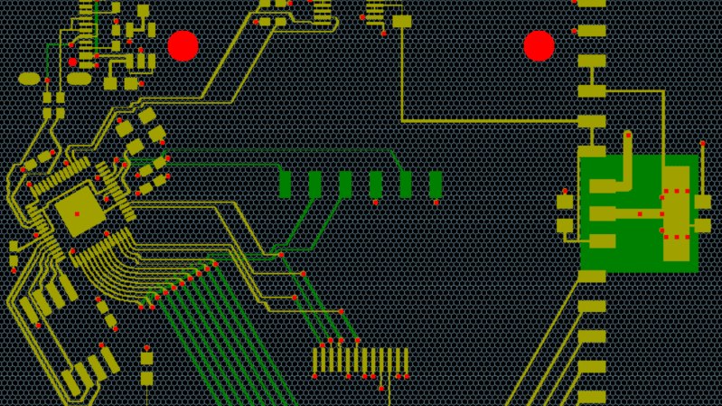
Despite the recent leaps forward in other forms of computer-driven design, the reliability of PCB autorouters remains questionable; on the positive side, though, the lack of massive training data makes them plausible for a determined programmer to implement. For anyone contemplating this undertaking, [James Bowman] recommends a slightly unusual choice: use a hexagonal layout grid.
[James] built his own autorouter in his CuFlow PCB layout program. It takes a fairly straightforward approach: it represents the board as a grid of cells, and uses Lee’s algorithm to find the shortest routes between connected cells. The program initially used a square grid, but a hexagonal grid had a few advantages: in particular, each cell has six equidistant neighbors, rather than four (or eight, if you accept diagonal neighbors at a different distance), which allows denser routing. Because a hexagon more closely approximates a circle than a square, the same minimum-distance rules allow smaller cells, allowing the autorouter to pack more traces into the same space.
While we have previously seen a self-built autorouter, it’s much more common to interface with an external tool. If you start to get into high-speed PCB routing, though, building an autorouter becomes much harder.