Sure, the physical build itself looks great, but it’s what [Michael] did with the firmware that impresses us the most. He’s using an Arduino Mega to drive the 7x7x7 cube and manages to squeeze out what he calls 142 frames per second with the setup. We’re not sure FPS is the right measurement, as we believe it’s the multiplexing rate that he’s trying to describle. It takes 144 uS to scan the entire matrix once. He performs the scan seven times per frame and the result is a flicker-free appearance, even to cameras.
You can see a video demonstration after the break. Since [Michael] emailed us directly with more details about the build we’ve pasted those below the fold as well.
If you’re looking for a more entry-level Arduino LED cube this 4x4x4 project is just the thing.
The cube is able to process 142 frames per second, that is, 1 frame every 7 milliseconds. Within this time period, it loops through a still frame 7 times (Each cycle of POV lasts 144 microseconds). This is able to compensate for flickering during video recording, allowing all camera’s to record fluid video without distortion.
The cube itself is controlled with an Arduino Mega 2560. For each frame in memory, the Arduino reads and bit shifts 49 bytes of data for an encoded duration. This allows for the cube to be applied to a variety of purposes, from text display to effects to music visualisation.
The frames were generated through complex Processing scripts, allowing for a multitude of operations such as shifting in any direction (seen in the rain effect), and an edge shift (seen in the scrolling text around the outside of the cube). These scripts were used to perform the basis of calculations for fireworks, as well as sine waves in 1, 2 & 3 dimensions (seen in the video).
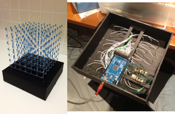
In this cube the supporting structure was made 0.9 mm galvanised steel wire, straightened by stretching the wire. The 5mm Blue LED’s are positioned 30mm apart, with the anodes being attached to the verticals (white wires in the image below) & the cathodes are attached to the horizontal layers (green wires in the image below – bottom right – shown passing through NPN transistors). The Arduino Mega 2560 R3 is positioned on a suspended platform, with the anodes controlled on the Digital Pins as opposed to the cathodes on remapped AnalogInputs.
Filed under: arduino hacks, led hacks The cube itself is controlled with an Arduino Mega 2560. For each frame in memory, the Arduino reads and bit shifts 49 bytes of data for an encoded duration. This allows for the cube to be applied to a variety of purposes, from text display to effects to music visualisation.
The frames were generated through complex Processing scripts, allowing for a multitude of operations such as shifting in any direction (seen in the rain effect), and an edge shift (seen in the scrolling text around the outside of the cube). These scripts were used to perform the basis of calculations for fireworks, as well as sine waves in 1, 2 & 3 dimensions (seen in the video).
In this cube the supporting structure was made 0.9 mm galvanised steel wire, straightened by stretching the wire. The 5mm Blue LED’s are positioned 30mm apart, with the anodes being attached to the verticals (white wires in the image below) & the cathodes are attached to the horizontal layers (green wires in the image below – bottom right – shown passing through NPN transistors). The Arduino Mega 2560 R3 is positioned on a suspended platform, with the anodes controlled on the Digital Pins as opposed to the cathodes on remapped AnalogInputs.

