
Almost a month ago I started trying to reverse engineer an inexpensive LED color changing light bulb. With your help I’ve mapped out the circuit, and taken control of the bulb. But there’s still a few mysteries in this little blinker. Join me after the break to see what I’ve done so far, peruse the schematic and source code, and to help solve the two remaining mysteries.
What I’ve Accomplished
First off, thank you to all the commenters on the original post. I figured a lot out about this circuit because of that help. Notably, that the code I had dumped wasn’t any use because the lock bits had been set. There was also a lot of constructive input and conjecture about this when I shared it at the Sector67 meeting on Tuesday (a hackerspace here in Madison).
I’m happy to say that I was able to program the ATtiny13 chip while in place. I damaged the first bulb I cracked open by drilling through an inductor. The second time I was more careful, and soldered ribbon cable onto each of the microcontroller pins.

I can program this chip without removing it from the board. This is accomplished by using High Voltage Serial Programming (HVSP) while AC power is not connected. I reset the fuses to factory settings to enable the reset pin but I have been unable to program this using ISP. But that’s not really a problem.*The diffuser was taped in place and I added an IDC connector for easy interface with the bulb.
The firmware I’ve written is up on GitHub. It has a few features; the default operation is to fade between red and green every 20 minutes as a porch light during this Christmas season. I’ll discuss the circuit below, but there are two unused pins on the device and I’ve added two test modes that are entered by jumping the pin to ground on the IDC connector. One of the test modes makes the red/green fader happen every 2 seconds. The other scrolls through primary and secondary colors with a 1/2 second delay.
So what we have is a microcontroller that drives two RGB LED modules in series. This chip has two available pins and 1K of programming space. So it should be relatively simple to make this into an I2C addressable module. Ideally this would be done without using AC power, sparking one of the questions I ask at the bottom of the post.
The Circuitry
I traced out the circuit board and recreated the schematic using an Ohmmeter and continuity Tester. There are two separate schematics, one for the LED control circuitry and another for the power supply.
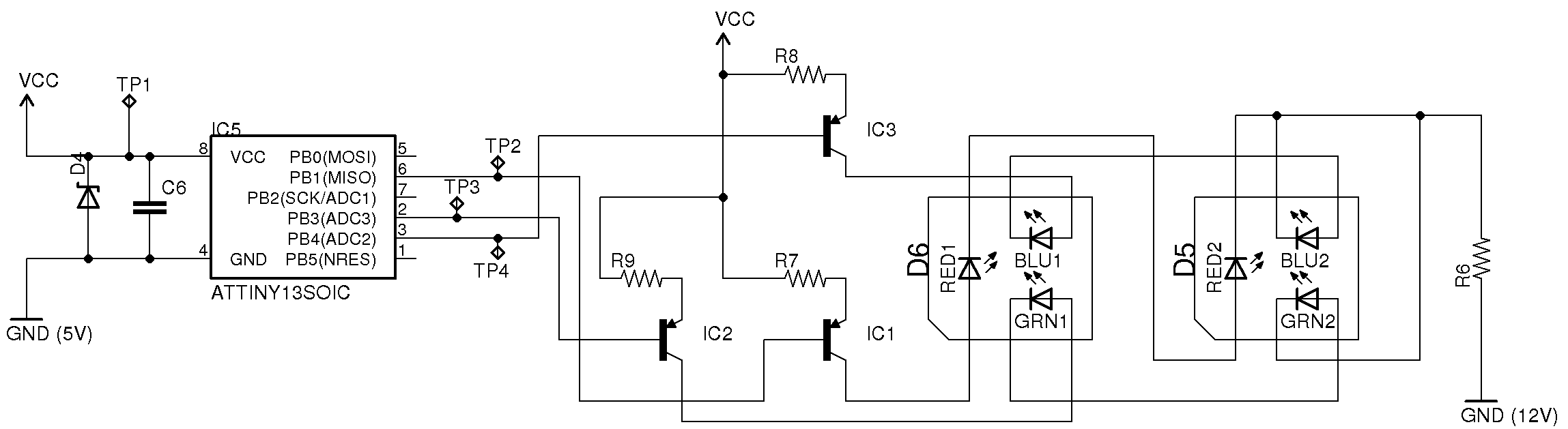

As expected, the power supply uses the example circuit from the LNK304 datasheet. The 12V output connects to the two VCC points on the controller schematic but the ground or return path is a bit peculiar. Look at the upper leg on the PSU schematic which includes R2, R3, R10, and C7. I’ve labeled this as ‘GND (5V rail)’ because this connects to the ground side of the ATtiny13. The ‘GND (12V rail)’ connects to the low side*of the LEDs but that is separated from the microcontroller ground path. Obviously the Zener diode is clamping power input for the microcontroller (which needs 5V), but I have no idea how the filter circuit leading back to the AC hot is working.
Take a look at the component list and then see if you can help solve two questions.
- R1 – inline with center conductor of light socket; ~0.5 Ohm. Might be a fuse
- R2 – 1004
- R3 – 1004
- R4 – 3001
- R5 – 1302
- R6 – 1201
- R7 – 1Bx
- R8 – 270
- R9 – 270
- R10 – 1003
- D1 – 1N4007
- D2 – 1N4007
- D3 – R106 TF
- D4 – Looks like a zener
- D5 – RGB LED
- D6 – RGB LED
- D7 – JF S1J
- IC1 – PNP Transistor
- IC2 – PNP Transistor
- IC3 – PNP Transistor
- IC4 – LNK304GN AC/DC switching converter
- IC5 – ATtiny13
- C1 – smd without label
- C2 – 50V 22 uF electrolytic
- C3 – 400V 4.7 uF electrolytic
- C4 – 400V 4.7 uF electrolytic
- C5 – 25V 100 uF electrolytic
- C6 – smd*without label
- C7- smd*without label
- L1 – 102J CEC
- L2 – 102J CEC
1. How does the GND connection for the ATtiny13 work? A complete answer will explain what the path that includes R2, R3, R10, and C7 actually does, and how it works in conjunction with the switching converter.
2. What is the easiest way to power the control circuit using DC?
Feel free to leave a comment with your thoughts. But if you’re so inclined, I’d love to read a more verbose description so post your thoughts on your own host and leave a link in the comments.
Follow Me
szczys
Filed under: HackIt


