Over a year ago, we took a look at importing a
.step file of a KiCad PCB into FreeCAD, then placing a sketch and extruding it. It was a small step, but I know it’s enough for most of you all, and that brings me joy. Today, we continue building a case for that PCB – the delay is because I stopped my USB-C work for a fair bit, and lost interest in the case accordingly, but I’m reviving it now.Since then, FreeCAD has seen its v 1.0 release come to fruition, in particular getting a fair bit of work done to alleviate one of major problems for CAD packages, the “topological naming problem”; we will talk about it later on. The good news is, none of my tutorial appears to have been invalidated by version 1.0 changes. Another good news: since version 1.0, FreeCAD has definitely become a fair bit more stable, and that’s not even including some much-needed major features.
High time to pick the work back up, then! Let’s take a look at what’s in store for today: finishing the case in just a few more extrusions, explaining a few FreeCAD failure modes you might encounter, and giving some advice on how to make FreeCAD for you with minimum effort from your side.
As I explained in the last article, I do my FreeCAD work in the Part workbench, which is perfectly fine for this kind of model, and it doesn’t get in your way either. Today, the Part and Sketcher workbenches are all we will need to use, so you need not be overwhelmed by the dropdown with over a dozen entries – they’re there for a reason, but just two will suffice.
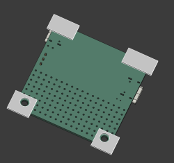
Last time, I drew a sketch and extruded it into a box. You’ll want your own starting layer to look different from that, of course, and so do I. In practice, I see two options here. Either you start by drawing some standoffs that the board rests on, or you start by offsetting your sketch then drawing a floor. The first option seems simpler to me, so let’s do that.
You can tie the mounting holes to external geometry from the STEP file, but personally, I prefer to work from measurements. I’d like to be easily able to substitute the board with a new version and not have to re-reference the base sketches, resulting in un-fun failure modes.
So, eyeballing the PCB, the first sketch will have a few blocks that the PCB will be resting on.
To The Floor And Beyond
Perfect – remember, the first sketch is already extruded, so when we re-drew the sketch, it all re-extruded anew, and we have the block we actually want. Now, remember the part about how to start a sketch? Single click on a surface so it gets highlighted green, press “New sketch”, and click “ok” on the box that asks if you want to do it the “Plane X-Y” way. That’s it, that’s your new sketch.
Now, we need to draw the box’s “floor”. That’s simple too – just draw a big rectangle. You’ll want to get some dimensions going, of course. Here, you can use the general distance constraint (K,D, click K then click D), or constrain even quicker by clicking I (vertical dimension) and L (horizontal dimension). Now, for the fun part – filleting! Simply put, you want to round the box corners for sure, nobody wants a box with jagged sharp holes.
You might have seen the Fillet tool in the Part workbench. Well, most of the time, it isn’t even needed, and frankly, you don’t want to use it if a simpler option exists. Instead, here, just use a sketch fillet – above in the toolbar; sadly, no keybind here. Then, click on corners you want rounded, exit the tool, then set their radius with diameter tool (D), as default radii are way too large at our scale. The sketch fillet tool basically just creates arcs for you – you can always draw the arcs yourself too, but it’s way easier this way.
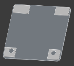
Extrude that to 1 mm, or your favourite multiple of your layer height when slicing the print, and that’s the base of your case, the part that will be catching the floor. Honestly, for pin insulation purposes, this already is more than enough. Feel free to give it ears so that it can be mounted with screws onto a surface, or maybe cat ears so it can bring you joy. If you’re not intimidated by both the technical complexity and the depravity of it, you can even give it human ears, making your PCB case a fitting hacking desk accessory for a world where surveillance has become ubiquitous. In case you unironically want to do this, importing a 3D model should be sufficient.
Build Up This Wall!
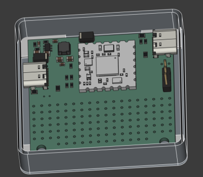
Make a sketch at the top of the floor, on the side that you’ll want the walls to “grow out of”. For the walls, you’ll naturally want them to align with the sides of the floor. This is where you can easily use external geometry references. Use the “Create external geometry” tool (G, X) and click on all the 8 edges (4 lines and 4 arcs) of the floor. Now, simply draw over these external geometry with line and arc tool, making sure that your line start and end points snap to points of external geometry.
To fix that, you can go box-select the intersection points with your mouse, and click C for a coincident constraint. Sometimes the sketch will fail. To the best of my knowledge, it’s a weird bug in KiCad, and it tends to happen specifically where external geometry to other solids is involved. Oh well, you can generally make it work by approaching it a few times. If everything fails, you can set distance (K,D) to 0, and if that fails, set vertical distance (I) and then horizontal distance (L) to zero, that should be more than good enough.
And with that, the wall is done. But it still needs USB-C socket holes. Cutting holes in FreeCAD is quite easy, even for a newcomer. You make a solid block that goes “into” your model exactly in the way you want the cut to be made. Then, in Part workbench, click the base model that you want cut in the tree view, click the solid block model, and use the “Cut” tool. Important note – when using the “Cut” tool, you have to first click on the base object, and then the tool. If you do it in reverse, you cut out the pieces you actually want to save, which is vaguely equivalent to peeling potatoes and then trashing the potatoes instead of the peels.
Stepping Up
Once you get past “Hello World”, and want to speed your FreeCAD work tremendously, you will want to learn the keybinds. Once again, the key to designing quickly and comfortably is having one hand on keyboard and another hand on mouse, doesn’t matter if you’re doing PCBs or 3D models. And the keybinds are very mnemonic: “d” is dimension, “c” is coincident.
Another tip is saving your project often. Yet another one is keeping your FreeCAD models in Git, and even publishing them on GitHub/GitLab – sure, they’re binary files, but revision control is worth it even if you can’t easily diff the files. We could always use more public 3D models with FreeCAD sources. People not publishing their source files has long been a silent killer of ideas in the world of 3D printing, as opposed to whatever theories about patents might be floating around the web. If you want something designed to your needs, the quickest thing tends to be taking someone else’s project and modifying it, which is why we need for sharing culture so that we can all finally stop reinventing all the wheels our projects may require.
This is more than enough to ready you up for basic designs, if you ask me. Go get that case done, throw it on GitHub, and revel in knowing your board is that much less likely to accidentally short-circuit. It’s a very nice addition for a board intended to handle 100 W worth of power, and now it can also serve as a design example for your own needs. Next time, let’s talk about a number of good practices worth attending to if you want your FreeCAD models to last.