Part of the fun with old computers is playing some old school games, and while you could play them with a keyboard it is much more fun with a joystick. You can get old joysticks all day long on auction sites, but you have to watch out. Some are digital, which wont work for many games on many systems. Some were cheap to begin with and probably worn out, and many are flight sticks … ever play pac-man with a giant flight stick?
What I really wanted was a game pad like device for my 1986 Apple //c , using one of the modern thumbstick analog controllers. Using a thumbstick out of an old XBOX(1) controller, some generic parts from Radio Shack, and a little bit of effort , I ended up with exactly what I wanted.
Join us after the break and I will show you how to get there!
First some basics, most computers that have analog controllers implement it in a pretty simple method. In a nutshell there is a 555 timer wired up for single shot mode, the computer triggers the 555 and counts how many cycles pass before the 555′s output changes. One of the potentiometers inside the joystick is hooked up to this circuit and controls the rate that a capacitor charges. Once filled the 555 changes output. Swing the joystick one way, resistance increases and the capacitor takes longer to charge. Swing it the other way resistance lowers, cap charges faster. Simple right?

Now just multiply 555′s for how many axis you need and you have a simple analog joystick. Apple //s, and IBMs work like this, and use a 556 dual timer (one, two axis joystick) or a 558 quad timer (two, two axis joysticks). Below is an example circuit from the Apple //c Technical Reference Manual.

Other computers like the 8 bit Commodore’s and Atari’s used this setup for their paddle controllers which were often in joystick or flightstick format. About the only one I know of that does not handle analog joysticks in this manner is the Tandy TRS series, but I am sure there are others. Check with your computers nerd club before proceeding.
Next thing to consider is the values of the potentiometers inside of your joystick. the most standard value for old computers is 100K ohm. Apple used 150K ohm. Why? I don’t know but with Apple stuff, if its hard to source, they will use it. Thumbsticks themselves come in all varieties of resistance, from places like Digikey. If you don’t mind spending a couple bucks + postage, that might be the best way for you.
Since I am using scavenged thumbstick from an XBOX controller I don’t have a choice of what value it is. The thumbsticks that come stock with that controller is 10K ohm. In order to compensate for the difference in resistance,we just need to add more capacitance.
Before I go bothering myself with math, I need to find out exactly where my joystick “tops out” while its in its enclosure. I went out an purchased a 4x2x1 inch enclosure from Radio Shack, and while I was there I also picked up a couple panel mount normally open pushbutton switches.
With these radio shack project boxes, they give 2 choices of a lid, a nice molded plastic lid that sits on top of the box, and an aluminum panel that sits a bit recessed in the box. I just had to have that aluminium panel for looks, but it ended up causing a bunch of problems.
First I had to cut the lip of the box off where the panel would not be recessed anymore. That was accomplished using some 90 degree flush cut wire trimmers and a file. Because I lost about a quarter of an inch in height, the thumbstick would not fit anymore using the screw mounts inside the box. I had to snap off the screw mounts, then flatten the area where they broke off with a chisel. Then I surface mounted everything to a piece of pad-per-hole perfboard flipped upside down, since the only way the thumbstick would fit is if the board was flat against the bottom.


With all of that sorted out, I went to drill holes into the aluminum panel. I drew the outline of the panel on some paper, and I was measuring everything out. I didn’t like how the holes were sitting, so in the end I just simply eyeballed them on paper. Then I taped the paper to the aluminum plate and made divots for the hole centers with a hammer and nail.

The aluminum plate was then screwed to a scrap chunk of 2×4 wood, and drilled. I used a 1 inch hole saw for the joystick (which is a bit too large) and quarter inch holes for the switches. I used a jewelers file to quickly deburr the holes, but the large joystick hole was still a little rough. To give a more finished appearance I decided that it needed a grommet.

I went to the local hardware store, and when I asked for a grommet with about a 1 inch inside diameter, they looked at me like I just stabbed a baby. I ended up at Lowes where I found a grommet in one of the “hard to find” bins in the screw section with a 1&1/8th outside diameter, and a 23/32nds inch (18.25 ish mm) inside diameter, which is good enough. The grommet was much too tall to fit both inside and outside of the box, so I just simply chopped its top off and glued it down with some goop (super strong and thick glue).
Now that the box is in order I can see where my thumbstick tops out at. I bent the leads of the thumbstick out to a 90 degree angle so I could surface mount them to the perfboard. Then I soldered it down and added some test leads, ran the wires out of a hole I drilled in the back of the box for the joysticks cable, and popped on the lid.


Using a multimeter I found out that it the furthest I could push the thumbstick came out to about 8.5K ohm on both axis. My meter is overkill for most of what I do, so I could have used the 5 digits of accuracy, but its not needed. I will add some trimpots later for fine tuning.
Now that I know 8.5K is my max resistance, its time to figure out how much capacitance I need to add so that the circuit internal to the computer will behave the same with this 10K pot as it did with a 150K. The formula to calculate the capacitance is pretty simple:
((original_potentiometer_value * internal_timing_capacitor) / new_potentiometer_value) – internal_timing_capacitor
Most of the time the internal timing capacitor is 0.022 uf, though you might want to check before assuming for your machine. The original potentiometer value of the Apple // is 150K ohm so…
((150,000 * 0.022) / 8500) – 0.022 = 0.366235294
Therefore we need to add about 0.36uf in parallel to the joystick so that a 10K pot works the same as a 150K pot in the timing circuit. My capacitor selection pretty much stinks so I ended up using 3, 0.1uf capacitors in parallel and 2, 0.1uf in series per axis, giving me about 0.35uf. It does not have to be exact because I also added a 10K trimpot in series with the capacitors which will allow me to control how fast the extra caps charge, giving a fine tuning mechanism. Below you will see the schematic I ended up with for my Apple //c.

Now it is just a matter of wiring everything up, connecting buttons and a cable, and then using a test program to calibrate the thumbstick. The Apple //c has a nice diagnostic program which also test’s joysticks, but you could just as easily write one up in basic. For example, in Applesoft:
10 X=PDL(0): FOR I=1 TO 10: NEXT: Y=PDL(1)20 PRINT X " " Y " " PEEK(49249) , PEEK (49250)30 GOTO 10To calibrate I just need to adjust the trimpots until its about center, the program above shows value from 0-255, and we can give ourselves about 5% in error, from there its just a matter of making sure the thumbstick maxes the readouts when in its most extreme up/down/left/right positions. Some error is ok, and a little jitteryness in center is fine as well.
Anyone who has programmed for analog controllers quickly figure out a little dead space for middle and a little room for error on the extremes is needed whether it be a 26+ year old computer, or a brand new Sony PSP, nothing is 100% perfect.

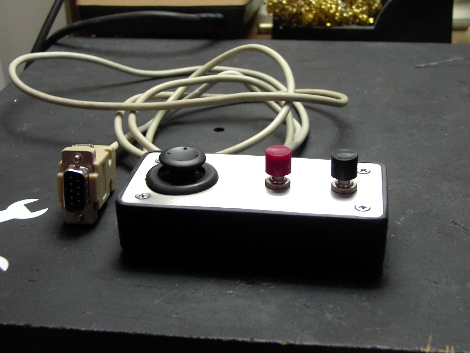
Once the thumbstick is calibrated to the computer its time to button it up and play some retro games. How well does it work? Pretty darn good, I may go back and drill a couple small holes so I can fiddle with the trimpots without having to take it apart, but other than that it plays good and looks nice (IMO) .

Thanks for reading!
(Reference: The Computer Controller Cookbook)
Filed under: how-to, news, peripherals hacks 


